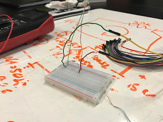
The goal is to understand the difference between nodal and mesh analysis. Nodal analysis is easier with current sources and mesh analysis is easier for voltage sources. If we are asked to find the currents in a circuit, then we would use mesh analysis. If asked to find voltages, we use nodal analysis. The main key is to use the easiest method for which will acquire the least number of equations. We are also introduced to transistors which are modeled as active devices. Furthermore, we will learn how to do circuit analysis of transistors and time based analysis (Time based measurements).
Group Practice:
1. The first problem that we worked on required the use of mesh analysis as seen in Figure 1. We used 3 mesh currents i1, i2, and i3 and used ohms law to express the voltages. However, We learned a new and easier way to solve the problem as seen in Figure 2.
 |
| Figure 1. A circuit problem in which mesh analysis is used. |
 |
| Figure 2. A new way of solving for the currents without much calculations. |
2. In figure 3, we have a transistor circuit and are told to find the Ib, Ic and Vo. In order to start, we need to create an equivalent model as seen in figure 3 below the first model. We use mesh analysis and find that Ib = .165 mA, we find Ic = BIb = 50(.165) = 8.25mA. Finally we find V0 by using mesh analysis where -V0 -100(.00825)+6 = 0, so V0 =5.18V
 |
| Figure 3. Calculations for Ib, Ic , and Vo in a transistor circuit. |
1. In order to start with our experiment, we calculated the theoretical values for V1 and I1 as seen in Figure #. We acquired values of V1 = 5.018V and I1 =-.322mA using mesh analysis and solving for the currents using MATLAB as seen in Figure 5. Though, it is important to note that our resistance for the 20 kilo ohm resistor was changed to a 22 kilo ohm resistor since it is the only closest resistance for a resistor in class.
 |
| Figure 4. Theoretical calculations for V1 and I1 |
 |
| Figure 5. Matlab is used to find the currents of the three meshes seen in Figure 4. |
2. We constructed a a circuit as seen in figure 6. However we first measured actual resistance values from our resistors used which are: R20K = 21.6K=/-.05, R10K =9.7K+/-.05, R4.7K = 4.5K+/-.05, R6.8K = 6.5K+/-.05.
 |
| Figure 6. Schematic of circuit in which the resistance of the resistors are not within the actual values. |
3. The experimental measurements are V1 = 4.96+/-.05 and I1 =-.318 +/- .05 in the circuit.
 |
| Figure 7. Resistance of I1 |
 |
| Figure 8. Voltage of V1 |
4. Based on our theoretical and experimental measurements, we can calculate for the percent error where % error = | (experimental-theoretical) | / theoretical * 100 . Our percent error for Voltage is 1.15% We can see that out theoretical calculations does accurately fall within our experimental measurements since our percent error is low.
Time Varying Signals Lab Procedures and Results:
1. We practiced using a arbitrary waveform generator to generate time varying signals.
2. We set a circuit where there is a voltage divider as seen in Figure 9 and 10.
 |
| Figure 9. A circuit where there is a voltage divider relation |
 |
| Figure 10. Using Oscilloscope to measure varying signals |
Summary of Labs and Overall Learning Outcome:
The schematic of the circuit with meshes and values may be seen in Figure 4 with the use of Matlab calculations for currents in Figure 5. We acquired theoretical measurements of V1= 5.018 and I1 =-.322mA . From our experimental measurements, we acquired values of V1 = , I1 =, and actual resistance values for each resistor where R20K = 21.6K=/-.05, R10K =9.7K+/-.05, R4.7K = 4.5K+/-.05, R6.8K = 6.5K+/-.05. We can concluded that our theoretical values do not have a significant difference with our experimental measurements since the percent error was a low 1.15% for voltage at V1 and a low 1.36% for current at I1. Using mesh analysis does in fact show useful and accurate values in a theoretical manner. In the end of class and for the last ab of the day we used the Oscilloscope to measure a varying signal from a voltage divider as seen in Figure 9 and 10.
No comments:
Post a Comment