The goal for today's class meeting is to review the idea of capacitors in circuits. Capacitors are devices that store electrical energy in the electric field. There are two plates which are usually aluminum since they are cheap to use. Also, the plates are oppositely charged. The voltage between the capacitor plates is V=Q/C where C = (epsilon)*A/d can be replaced. We can also find the equivalent capacitance which is almost related the equivalent resistance but opposite. In other words, when capacitor are in parallel, they are added together. When the capacitors in series, they are inversely added. We also covered and reviewed inductors which are coils with many loops that oppose rapid changes in current. The voltage difference between an inductor is V = L*di/dt. We will use this idea for the lab by using the oscilloscope and waveform generator.
Group Practice:
1. The image below is an experiment that shows a capacitor being blown up due the having the positive voltage terminal input being connected to the negative side of the capacitor. The positive side or plate of the capacitor is connected to the negative input terminal. This makes the capacitor expand due the liquid salt inside the capacitor that makes it expand and explode.
 |
| Figure 1. Set up of blowing up a capacitor when the voltage inputs are connected in the opposite direction. |
2. We are given a problem where we are told to find the voltages at the capacitors. In order to this, we will assume that the capacitors act like an open switch. We can then use current division and find the current flowing through the 3k,2k and 4k resistor. Figure 2 shows how to find the current. We can then find the voltages at 4k and 2k resistors which are actual voltages of the capacitors since they are parallel to each other.
 |
| Figure 2. A circuit in which there are capacitors. |
3. We are given a voltage equation in terms of t and an initial current at t=0, We are told to find the current in a circuit where there is an inductor. We use integration as seen in figure 3 and solve for current through the conductor.
 |
| Figure 3. A problem in which we must solve for the current flowing through the inductor and the energy. |
1. Before we start the lab, we are required to do a pre lab that will give us an idea on what we expect for our capacitor current when when sinusoidal and triangle wave voltage is applied. As seen in figure 4, since i=Cdv/dt, we can calculate the current by taking the derivative of the voltage input.
 |
| Figure 4. A plot that shows a voltage signal and the expected current. |
 |
| Figure 5. Schematic for circuit where there is a voltage source connected in series with resistor and capacitor. |
 |
| Figure 6. Actual circuit build. |
 |
| Figure 7. Results when frequency is 1kHz with a sinusoidal voltage. |
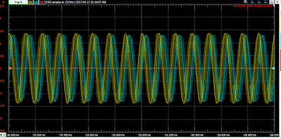
5. The next step is to change the f = 2kHz. The results can be seen in figure 8.
 |
| Figure 8. Results when frequency is 2kHz |
6. The final step is to apply a triangular input voltage with f = 100Hz, A = 4V, and offset=0V. The result can be seen below. The voltage difference across the capacitor is in yellow and the voltage input is in blue. The current of the resistor is in orange.
 |
| Figure 9. Results when f =100Hz with a triangular voltage input. |
Inductor Voltage-Current Relations Lab Procedures and Results:
1. The image below is similar to the previous lab. However, there is a inductor in this case. The actual circuit set up can be seen in figure 11.
 |
| Figure 10. Schematic of a voltage input connected to a resistor and inductor in series. |
 |
| Figure 11. Actual circuit. |
2. We apply a sinusoidal input voltage with f =1kHz, A = 2V, and offset= 0V. The yellow is the voltage across the resistor. The blue wave represent that voltage difference between the inductor and the orange is the current through the resistor.
 |
| Figure 12. Results when f=1kHz |
3. The frequency is then changed to 2kHz to acquire new results as seen in figure 13.
 |
| Figure 13. Results when F =2Khz |
4. A triangular voltage is applied to the inductor and resistor and acquire new results.
 |
| Figure 14. Results when triangular wave is introduced. |
Our assumed results in figure 4 relates to our results from figure 7 and 9 in terms of voltage input and the voltage difference across the capacitor. Out theory shows accurate based on our results for the voltage but not the current and the voltage across the capacitor. Unfortunately, there was a mistake entering our mathematical input for the current across the capacitor. Instead, we measured the current across the resistor which was not necessary which is represented by the orange wave line. The same procedure is produced to inductor voltage-current relations lab. We came to the conclusion that it looks similar to the results from the capacitor voltage-current relations lab. The main problem in both lab is that we did not measure the current across the capacitor and inductor which will show whether or not out assumed results for voltage- current relations hold true for a capacitor.
No comments:
Post a Comment